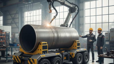
Weld Roller Carriage systems help fabrication teams rotate large cylindrical workpieces during welding, inspection, and coating operations. They reduce manual repositioning and keep the joint within a more stable working zone. In practical terms, a vessel shell rests on powered rollers, while an operator adjusts rotation speed through a control panel. The weld torch stays relatively steady as the component turns beneath it.
This equipment matters because industrial welding is becoming more automated and production-focused. MarketsandMarkets estimates that the global welding equipment market could grow from about USD 16.6 billion in 2023 to USD 21.2 billion by 2028. That expansion reflects demand from shipbuilding, pressure-vessel production, construction machinery, and energy infrastructure. A Weld Roller Carriage supports these sectors by improving positioning consistency and reducing avoidable handling time. It does not replace skilled judgment.
That distinction matters.
The American Welding Society emphasizes procedure control, qualified personnel, and inspection in its welding standards, including AWS D1.1. A roller carriage can support those requirements, but it cannot correct poor fit-up, incorrect heat input, or contaminated surfaces. Grand View Research also identifies automation and productivity as major forces shaping the welding equipment market. However, market forecasts are not guarantees. Actual performance depends on load capacity, roller alignment, motor torque, surface condition, and operator training. This guide explains how the system works, where it performs well, and which limitations deserve closer attention. A small alignment error can become a visible weld problem. That detail is easy to underestimate.
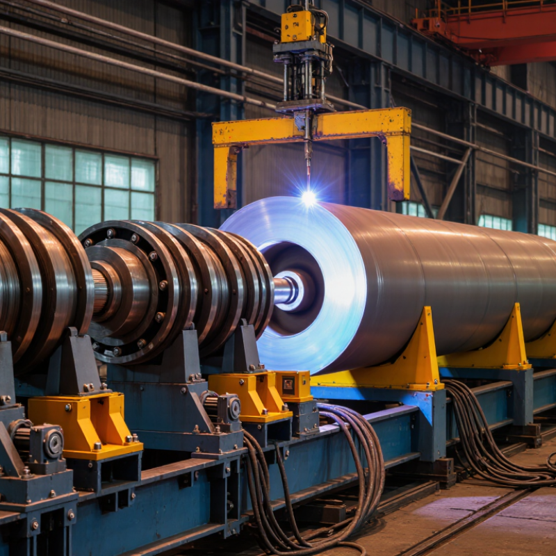
A weld roller carriage is a powered support system for rotating cylindrical workpieces during welding. It usually includes two or more adjustable roller units, a steel frame, a drive motor, and controls. The rollers carry vessels, pipes, tanks, or other round fabrications. As they rotate the workpiece, the carriage helps maintain a steady welding position.
Its purpose is practical: reduce manual repositioning, improve weld access, and support more consistent travel speed. Operators can set the rotation rate to match the welding process and joint size. Load capacity, roller diameter, alignment, and surface condition require careful checking. Small errors can cause slipping or uneven heat distribution. That detail is often underestimated.
The need is significant. The World Steel Association reported approximately 1.89 billion tonnes of crude steel production in 2023, creating demand for efficient fabrication equipment. In addition, the International Federation of Robotics recorded about 542,000 industrial robot installations worldwide in 2023. These figures show a wider movement toward controlled production, although a roller carriage is not automatically a robotic system. It may operate through simple manual controls or integrate with automated welding equipment. According to ISO 17637, visual inspection remains important for detecting surface defects. Rotation improves access, but it does not replace inspection, operator judgment, or correct welding procedure qualification.
A weld roller carriage supports a cylindrical workpiece and rotates it during welding. The required roller speed depends on the workpiece diameter and the selected surface welding speed.
The chart uses a constant surface speed of 300 mm/min. Rotational speed is calculated as RPM = surface speed ÷ (π × workpiece diameter). Larger diameters require lower rotational speed to maintain the same welding travel speed.
A weld roller carriage supports and rotates cylindrical workpieces during welding, inspection, or surface preparation. It usually has a strong frame, drive rollers, idler rollers, and an adjustable carriage. The drive rollers receive power from an electric motor and gearbox. Their controlled rotation keeps the joint moving beneath the welding torch. Idler rollers support the opposite side and reduce uneven loading.
The frame must resist vibration and keep the rollers aligned. Misalignment can cause a pipe to drift sideways. Adjustable roller spacing allows the carriage to handle different diameters. Some designs use rubber-coated rollers for better grip, while steel rollers tolerate heavier loads. A control panel regulates rotation speed, direction, and stopping. Low-speed control is important near the beginning and end of a weld. A remote pendant can let an operator adjust movement without standing beside the rotating workpiece.
Limit switches and overload protection add another layer of control. They can stop movement when travel becomes unsafe or the motor meets excessive resistance. In practical workshop use, clean roller surfaces matter more than many operators expect. Oil, scale, or spatter may cause slipping. That creates inconsistent weld speed. It is easy to blame the motor first. The rollers may be the real problem. Regular checks should include gearbox noise, cable condition, roller wear, and frame fasteners. I would also verify the actual rotation speed, because a displayed setting may not match movement under load.
A weld roller carriage supports and rotates cylindrical workpieces during welding. Its powered rollers contact the vessel, pipe, or tank shell. The operator first checks diameter, weight, and center of gravity. The carriage is then positioned on a firm, level floor. Adjustable rollers are set to keep the workpiece centered. This step matters because poor alignment can create uneven rotation and unstable weld travel.
The operator loads the workpiece slowly, usually with approved lifting equipment. The rollers must touch evenly before rotation begins. Next, the control system starts at low speed. The operator watches for slipping, vibration, and abnormal noise. Once movement is stable, the speed is adjusted to match the welding procedure. The welder maintains a steady torch angle while the carriage turns the joint through the required position. A foot control or pendant can stop rotation quickly. AWS’s Welding Industry Outlook has estimated that the American welding sector may need 330,000 new professionals by 2028. That pressure makes repeatable equipment operation increasingly valuable, although automation cannot replace sound inspection judgment.
Tips: Clean roller surfaces before loading. Check the emergency stop every shift. Measure actual rotation speed, not only the display. In practice, the first trial rotation may not be perfect. A slightly uneven shell can reveal alignment errors. Reposition the carriage, reduce speed, and inspect the contact points before welding. Keep cables clear of moving parts, and record load settings for similar workpieces.
| Step | Operating Stage | Main Components Involved | How the Weld Roller Carriage Works | Typical Operator Check or Result |
|---|---|---|---|---|
| 1 | Position the carriage | Base frame, wheels, rails or prepared floor surface | The carriage is placed on a stable, level path so that it can travel parallel to the workpiece. A rail-guided design uses fixed rails, while a floor-running design uses wheels designed for a prepared surface. | The carriage sits evenly, the travel path is clear, and the wheels or guide rollers are free from visible damage. |
| 2 | Inspect the workpiece | Cylindrical vessel, pipe, tank shell, or fabricated section | The workpiece is checked for suitable geometry, surface condition, and weight distribution before it is placed on the rollers. The load must remain within the carriage's rated capacity. | The workpiece dimensions, weight, center of gravity, and support points are confirmed against the equipment instructions. |
| 3 | Set the roller spacing | Adjustable roller beds, screw mechanisms, hydraulic adjustment, or sliding supports | The distance between roller assemblies is adjusted to support the workpiece without causing excessive overhang. Self-aligning designs allow the rollers to accommodate certain diameter changes as the load is positioned. | Both roller assemblies contact the workpiece securely, and the load is supported without rocking or excessive side movement. |
| 4 | Load the workpiece | Drive rollers, idler rollers, lifting equipment, and load supports | Lifting equipment places the workpiece onto the roller sets. The drive and idler rollers transfer the load through their contact surfaces while maintaining rotational support. | The workpiece is centered as required, the rollers are fully engaged, and no part of the load interferes with the frame. |
| 5 | Secure and align the load | Side guides, anti-drift devices, stops, and alignment controls | Guides or anti-drift controls limit unwanted axial movement. Alignment is adjusted so the workpiece rotates smoothly without climbing the rollers or moving sideways. | The workpiece remains within the intended operating zone and has sufficient clearance from nearby equipment and personnel. |
| 6 | Select the rotation direction | Control panel, pendant, variable-frequency drive, and motor controls | The operator selects forward or reverse rotation. The control system regulates motor output and sends power to the drive rollers through a gearbox, chain drive, or other mechanical transmission. | The selected direction matches the planned welding position and the emergency-stop control is accessible. |
| 7 | Start at low speed | Electric motor, gearbox, drive roller, and speed controller | The motor produces torque, the gearbox reduces speed and increases usable torque, and the drive roller transfers frictional force to the workpiece. Starting slowly reduces sudden movement. | The workpiece starts smoothly, without slipping, abnormal vibration, severe noise, or rapid lateral movement. |
| 8 | Rotate at welding speed | Drive rollers, idler rollers, motor controller, and operator controls | Continuous roller rotation turns the workpiece while the welding torch or operator remains positioned near the joint. Rotation speed determines the travel speed around the circumference. | The selected speed remains steady and provides a controlled welding pace suitable for the joint, process, and welding procedure. |
| 9 | Maintain alignment during welding | Roller surfaces, guide mechanisms, bearings, and frame | The rollers support the workpiece and maintain rotation while the operator monitors alignment. Even contact and correct load distribution help prevent wobble and inconsistent torch-to-work distance. | The joint remains aligned, the rotation is consistent, and the workpiece does not bind against the guides or frame. |
| 10 | Stop or index the workpiece | Brake function, stop control, controller, and position reference | The operator reduces speed and stops the drive when a weld segment, inspection point, or repositioning step is reached. Controlled stopping helps prevent overshoot. | The workpiece stops without excessive coasting, and the weld area is held in the required position for inspection or restart. |
| 11 | Reverse or reposition if required | Forward/reverse control, drive rollers, and alignment guides | Reverse rotation moves a selected section back into position. The drive system changes direction only after the workpiece has been brought to a controlled stop. | Direction changes are deliberate, controlled, and free from sudden load movement or roller slippage. |
| 12 | Unload and inspect | Lifting equipment, roller bed, frame, and inspection tools | After welding and cooling requirements are satisfied, the workpiece is removed using suitable lifting equipment. The carriage is then checked for damage, debris, and unusual wear. | The finished workpiece is safely removed, the carriage is left stable, and rollers, guards, cables, and controls are ready for the next operation. |
A weld roller carriage supports and rotates cylindrical workpieces during welding. Its rollers carry the load while a geared motor controls rotation speed. This movement keeps the welding position steady and reduces repeated repositioning. A foot control or pendant usually allows fine adjustments near the weld area.
Common types include conventional roller carriages, self-aligning carriages, and fit-up turning rolls. Conventional models use adjustable roller spacing for different diameters. Self-aligning models pivot slightly as the workpiece rotates. They are useful when vessel dimensions vary. Fit-up rolls provide stronger positioning before welding, especially for thick shells and large pipe sections. Powered rollers drive the workpiece, while idler rollers support it without independent drive power.
Different industries choose different arrangements. Fabrication shops use them for storage tanks, pressure vessels, heat exchangers, and structural pipe. Shipyards may rotate large sections during seam welding.
Energy projects often use heavy-duty systems for towers, tubular frames, and process equipment. A smaller portable carriage can handle repair work in restricted spaces. It is convenient, but capacity limits are easy to underestimate.
In practice, clean rollers matter. Oil, scale, or uneven contact can cause slipping and irregular weld speed. Operators also check load distribution before rotation. A workpiece may look centered but still drift under torque. That small error can damage a seam or strain the carriage.
Engineers should verify diameter, weight, surface condition, and required rotation speed before selecting equipment. No single roller type fits every workshop.
A weld roller carriage supports cylindrical workpieces during welding, coating, or inspection. Its powered rollers rotate the vessel at a controlled speed. This movement keeps the weld area accessible and reduces repeated repositioning. Most systems include adjustable roller spacing for different diameters. Some use separate drive and idler units, while others use synchronized roller sets. The correct load rating matters, even when the workpiece appears stable.
Safety begins with level installation and accurate alignment. Check the carriage before every shift for cracked welds, loose bolts, damaged cables, and unusual roller noise. Keep hands, clothing, and tools away from rotating surfaces. Use mechanical restraints when the cylinder could move sideways. Never exceed the rated load or operating speed. A small alignment error can create dangerous movement. It can also produce uneven weld quality. Maintenance should include cleaning metal dust, lubricating approved points, and inspecting brakes, controls, and bearings. Maintenance records help reveal gradual problems that operators may overlook.
Tips: Measure the workpiece diameter, length, weight, and center of gravity before choosing a carriage. Confirm that the rollers can support the actual shape, not only its average weight. Test rotation at low speed first. Listen carefully. A brief vibration may indicate poor alignment, worn bearings, or an uneven surface. Selection is not always simple; a higher capacity model is not automatically safer if its adjustment range is unsuitable. Get a qualified technician to review unusual loads or custom fixtures.